Chapter 1: Introduction to Arduino
What is Arduino?
Arduino is an open-source electronics platform based on easy-to-use hardware and software. It consists of a microcontroller board and an integrated development environment (IDE) for writing, compiling, and uploading code to the board. Arduino is popular among hobbyists, students, and professionals for prototyping, experimentation, and creating interactive electronic projects.
Brief History and Evolution
Arduino was created in 2005 by Massimo Banzi, David Cuartielles, Tom Igoe, Gianluca Martino, and David Mellis at the Interaction Design Institute Ivrea in Italy. The project aimed to provide an affordable and accessible platform for artists, designers, and anyone interested in creating interactive projects.
The first Arduino board, the Arduino Diecimila, was released in 2005. Since then, several variants and revisions have been introduced, each offering different features and capabilities. The Arduino Uno, introduced in 2010, became one of the most popular and widely used boards due to its simplicity and versatility.
What Can You Do with Arduino?
With Arduino, the possibilities are virtually endless. You can use it to:
Create interactive art installations.
Build home automation systems.
Prototype electronic gadgets and devices.
Develop educational tools for teaching electronics and programming.
Experiment with sensors, actuators, and communication protocols.
Chapter 2: Understanding Arduino Boards
Different Types of Arduino Boards:
Arduino Uno:
The Arduino Uno is one of the most popular Arduino boards, featuring the ATmega328P microcontroller.
It has 14 digital input/output pins (of which 6 can be used as PWM outputs), 6 analog inputs, a 16 MHz quartz crystal, a USB connection, a power jack, an ICSP header, and a reset button.
Ideal for beginners and intermediate users for a wide range of projects.


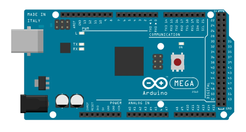
Arduino Mega:
The Arduino Mega is similar to the Uno but offers more I/O pins and memory.
It features the ATmega2560 microcontroller with 54 digital I/O pins (of which 15 can be used as PWM outputs), 16 analog inputs, 4 UARTs (hardware serial ports), a 16 MHz quartz crystal, a USB connection, a power jack, an ICSP header, and a reset button.
Suitable for projects requiring a large number of I/O pins or more processing power.
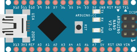
Arduino Nano:
The Arduino Nano is a compact version of the Uno, designed for smaller projects.
It features the ATmega328P microcontroller, 14 digital I/O pins (of which 6 can be used as PWM outputs), 8 analog inputs, a 16 MHz quartz crystal, a USB connection, and a mini-USB jack for programming and power.
Ideal for projects with space constraints or when a smaller form factor is desired.
Choosing the Right Arduino Board
When selecting an Arduino board for your project, consider the following factors:
Size: Choose a board size that fits your project's requirements. For small projects or projects with limited space, consider compact options like the Nano or Mini.
I/O Pins: Ensure the board has a sufficient number of digital and analog pins for interfacing with sensors, actuators, and other components in your project.
Processing Power: Consider the complexity of your project and whether it requires more processing power than the standard Uno can provide. Boards like the Mega or Due offer more memory and processing capabilities.
Special Features: Some Arduino boards come with built-in features like Wi-Fi, Bluetooth, or native USB support. Evaluate whether these features are necessary for your project.
Compatibility: Ensure compatibility with existing shields or add-on modules that you may want to use in your project.
Cost: Consider your budget and choose a board that meets your requirements without exceeding your budget.
Chapter 3: Getting Started with Arduino
Setting Up the Arduino IDE
Before you can start programming your Arduino board, you need to set up the Arduino Integrated Development Environment (IDE) on your computer. Follow these steps to set up the Arduino IDE:
Download the Arduino IDE: Visit the official Arduino website (https://www.arduino.cc/) and download the Arduino IDE for your operating system (Windows, macOS, or Linux).
Install the Arduino IDE: Once the download is complete, follow the installation instructions provided on the Arduino website to install the IDE on your computer.
Launch the Arduino IDE: After installation, launch the Arduino IDE from the desktop shortcut or the applications folder on your computer.
Configure Preferences: Before you start writing code, you may need to configure some preferences in the Arduino IDE. Go to the "File" menu and select "Preferences." Here, you can set options such as the language, font size, and compiler warnings.
Select the Board and Port: Before you can upload code to your Arduino board, you need to select the correct board and serial port. Go to the "Tools" menu, then select "Board" and choose your Arduino board model (e.g., Arduino Uno). Next, go to the "Tools" menu again, select "Port," and choose the serial port that corresponds to your Arduino board (e.g., COM3 on Windows, /dev/cu.usbmodem on macOS).
Writing Your First Arduino Sketch
Now that you've set up the Arduino IDE, it's time to write your first Arduino sketch (program). Follow these steps to write a simple sketch that blinks an LED connected to your Arduino board:
Open a New Sketch: In the Arduino IDE, go to the "File" menu and select "New" to open a new sketch.
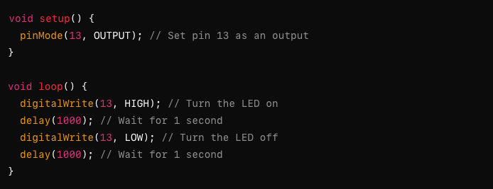
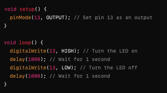
Write the Code: Type the following code into the Arduino IDE:
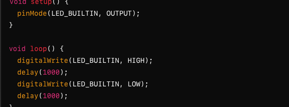
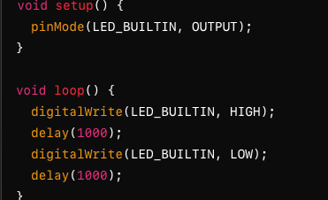
This code sets the built-in LED pin (pin 13 on most Arduino boards) as an output pin in the setup function. Then, in the loop function, it turns the LED on for one second, then off for one second, creating a blinking effect.
Upload the Sketch: Connect your Arduino board to your computer using a USB cable. Make sure the correct board and port are selected in the Arduino IDE. Then, click the "Upload" button (the right arrow icon) in the toolbar to upload the sketch to your Arduino board.
Verify the Output: After uploading the sketch, you should see the built-in LED on your Arduino board blinking on and off at one-second intervals.
Chapter 4: Understanding the Basics
Introduction to Microcontrollers
Microcontrollers are small, self-contained computers on a single integrated circuit (IC). They are designed to execute a specific task or set of tasks, making them ideal for embedded systems and electronic devices. Unlike general-purpose computers, which are capable of running a variety of programs and applications, microcontrollers typically run a single program or firmware that controls the device's behavior.
Arduino boards are based on microcontrollers, specifically those from the Atmel AVR and Atmel SAM series. The microcontroller serves as the brain of the Arduino board, executing the code (sketch) uploaded to it via the Arduino IDE. The most commonly used microcontroller in Arduino boards is the ATmega series, such as the ATmega328P found in the Arduino Uno.
Arduino Programming Language Basics
The Arduino programming language is based on C and C++, with some simplifications and abstractions to make it more accessible to beginners. Here are some key concepts and elements of the Arduino programming language:
Syntax Rules and Conventions: Arduino code is written in plain text and follows a set of syntax rules and conventions. These include rules for declaring variables, defining functions, and structuring control flow statements.
Variables: Variables are used to store data in a program. In Arduino, variables can be of different data types, such as integer (int), floating-point (float), character (char), boolean (bool), and more. Variables must be declared before they can be used, specifying their data type and optionally an initial value.
Operators: Operators are symbols used to perform operations on variables and values. Arduino supports various types of operators, including arithmetic operators (+, -, , /), logical operators (&&, ||, !), comparison operators (==, !=, <, >, <=, >=), and assignment operators (=, +=, -=, =, /=).
Control Structures: Control structures are used to control the flow of execution in a program. Arduino supports common control structures such as if statements, for loops, while loops, and switch-case statements. These structures allow you to make decisions, iterate over data, and execute code conditionally.
An Arduino sketch is the program written in the Arduino programming language that runs on the Arduino board. The sketch consists of two main parts: the setup function and the loop function.
Setup Function: The setup function is called once when the Arduino board is powered on or reset. It is used to initialize variables, configure pin modes, and perform any setup tasks required by the program. The setup function runs before the loop function.
Loop Function: The loop function is the main execution loop of the Arduino sketch. Once the setup function has completed, the Arduino board enters the loop function, where it repeatedly executes the code inside the loop. This allows the Arduino to perform tasks continuously, such as reading sensor data, controlling outputs, and responding to user input.
Use Libraries: Take advantage of existing libraries to simplify common tasks and access additional functionality. Arduino libraries provide pre-written code for interfacing with sensors, actuators, communication protocols, and more, saving you time and effort.
Anatomy of an Arduino Sketch
Chapter 5: Working with Pins
Digital vs Analog Pins
Arduino boards come with a combination of digital and analog pins, each serving different purposes:
Digital Pins: Digital pins can be configured as inputs or outputs. As outputs, they can be used to send digital signals (either HIGH or LOW). As inputs, they can read digital signals (either HIGH or LOW). Digital pins are commonly used for controlling LEDs, reading buttons, and interfacing with digital sensors.
Analog Pins: Analog pins can read analog signals, which are continuous voltages ranging from 0V to the reference voltage (typically 5V on most Arduino boards). Analog pins convert these analog signals into digital values using the analog-to-digital converter (ADC) built into the microcontroller. Analog pins are used for reading analog sensors, such as temperature sensors, light sensors, and potentiometers.
Pin Numbering and Mapping
Arduino boards have a specific numbering scheme for their pins, which may vary depending on the board model. It's essential to understand the pin numbering and mapping to effectively use the pins in your projects:
Digital Pin Numbering: Digital pins are numbered sequentially from 0 to the highest available pin number on the board. For example, the Arduino Uno has digital pins numbered from 0 to 13.
Analog Pin Numbering: Analog pins are also numbered sequentially, usually starting from A0. For example, the Arduino Uno has analog pins labeled as A0, A1, A2, up to A5.
Pin Mapping Diagrams: Refer to the pinout diagrams provided in the Arduino documentation or datasheets for your specific Arduino board model. These diagrams illustrate the pin assignments for digital and analog pins, as well as special-purpose pins (e.g., power, ground, communication interfaces).
Working with digital signals is fundamental in Arduino projects. Here's how you can read and write digital signals using Arduino:
Writing Digital Output: Use the 'digitalWrite()' function to set the output state of a digital pin. For example, to turn an LED connected to pin 13 on and off:
Reading and Writing Digital Signals
By understanding digital and analog pins, pin numbering, and how to read and write digital signals, you can effectively interface with external components and sensors in your Arduino projects
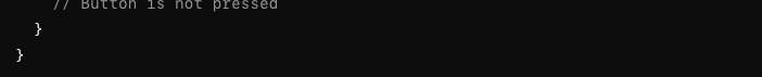
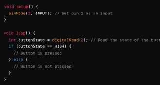
Reading Digital Input: Use the 'digitalRead()' function to read the state of a digital pin. For example, to read the state of a button connected to pin 2:
Chapter 6: Using the Serial Monitor
The Serial Monitor is a valuable tool in the Arduino IDE that allows you to communicate with your Arduino board via serial communication. It enables you to send data from your Arduino board to your computer for debugging, monitoring sensor readings, and receiving commands from your computer.
Enabling Serial Communication
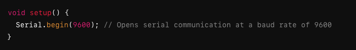
Before you can use the Serial Monitor, you need to enable serial communication in your Arduino sketch. This is done by calling the' Serial.begin()' function in the 'setup()' function of your sketch. You specify the baud rate (communication speed) as an argument to this function. For example:
The baud rate specified in 'Serial.begin()' must match the baud rate configured in the Serial Monitor.
Printing Data to the Serial Monitor
You can send data from your Arduino board to the Serial Monitor using the Serial.print() or Serial.println() functions. These functions work similarly to the standard print() and println() functions in C++.
For example, to send a sensor reading to the Serial Monitor:

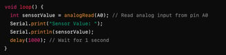
In this example, the 'analogRead()' function reads an analog sensor connected to pin A0, and the sensor value is printed to the Serial Monitor.
Viewing Data in the Serial Monitor
To view the data sent from your Arduino board, open the Serial Monitor in the Arduino IDE. You can do this by clicking the Serial Monitor button (the magnifying glass icon) in the toolbar. The Serial Monitor window will open, displaying the data sent by your Arduino board.
Ensure that the baud rate selected in the Serial Monitor matches the baud rate specified in your Arduino sketch.
Reading Serial Data
In addition to sending data from your Arduino board to your computer, you can also read data sent from your computer to your Arduino board. This allows you to send commands or configuration settings to your Arduino sketch.
To read data from the Serial Monitor in your Arduino sketch, use the 'Serial.read()' function. For example:

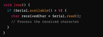
In this example, the 'Serial.available()' function checks if there is data available in the serial buffer. If data is available, it is read using the 'Serial.read()' function and stored in a variable for further processing.
Using Serial Communication for Debugging
The Serial Monitor is an invaluable tool for debugging your Arduino sketches. You can use it to print debug messages, sensor readings, and variable values to help diagnose issues in your code.
By mastering the Serial Monitor, you can effectively debug your Arduino projects, monitor sensor readings, and interact with your Arduino board in real-time.